Arduino network communications
May 15, 2021 Arduino
Table of contents
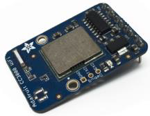
Texas Instruments' CC3000 WiFi module is a small silver bag that ultimately brings easy-to-use, affordable WiFi capabilities to your Arduino project.
It communicates using SPI instead of UART, so you can push data as fast or as slowly as you want. /b10> It has a suitable IRQ pin interrupt system, so you can have an asynchronous connection. /b11> It supports 802.11b/g, open/WEP/WPA/WPA2 security, TKIP and AES. /b13> The built-in TCP/IP stack with the "BSD socket" interface supports TCP and UDP in client and server mode.
The required component
You will need the following components:
- 1 × Arduino Uno
- 1 × Adafruit CC3000 sub-board
- 1 × 5V relay
- 1 × recting diodes
- 1 × LED
- 1 × 220 ohm resistor
- 1 × breadboard and some jumpers
For this project, you only need the usual Arduino IDE, Adafruit's CC3000 library, and CC3000 MDNS library. /b10> We will also use the aREST library to send commands to relays via WiFi.
Program
Connect according to the circuit diagram, as shown in the following image.
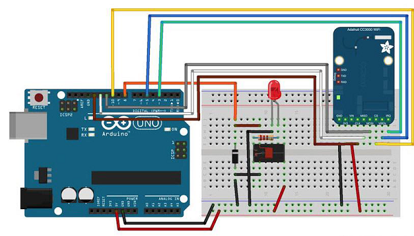
The hardware configuration for this project is very simple.
- Connect the IRQ pin of the CC3000 board to pin 3 of the Arduino plate.
- VBAT is connected to pin 5 and CS is connected to pin 10.
- Connect SPI pins to the Arduino board: MOSI, MISO, and CLK to pins 11, 12 and 13, respectively.
- Vin is connected to Arduino 5V and GND is connected to GND.
Now, let's connect the relay.
After you place the relay on the breadboard, you can begin to identify two important parts of the relay: the coil section indicating the relay and the switching part that connects the LED.
- First, connect the No. 8 pin of the Arduino plate to one of the pins of the coil.
- Connect another pin to the ground of the Arduino plate.
You must also place the rectation diode (the anode is connected to the ground pin) on the pin of the coil to protect the circuit when the relay switches.
-
Connect the Arduino board's .5V to the common pin of the relay switch.
-
Finally, connect the other pin of the switch (usually the one that is not connected when the relay is disconnected) to the LED in series with the 220 ohm resistor and connect the other end of the LED to the ground of Arduino.
Test individual components
You can test the relay with the following sketch:
const int relay_pin = 8; // Relay pin

void setup() {
   Serial.begin(9600);
   pinMode(relay_pin,OUTPUT);
}

void loop() {
   // Activate relay
   digitalWrite(relay_pin, HIGH);
   // Wait for 1 second
   delay(1000);
   // Deactivate relay
   digitalWrite(relay_pin, LOW);
   // Wait for 1 second
   delay(1000);
}
Code description
The code speaks for itself. All you have to do is upload it to the board, the relay switches states per second, and the LEDs light up and off accordingly.
Add a WiFi connection
Now let's use the CC3000 WiFi chip to control the relay wirelessly. /b10> The software for this project is based on the TCP protocol. H owever, for this project, the Arduino board will run a small Web server so that we can "listen" to commands from the computer. /b12> Let's take a look at the Arduino sketch, and then we'll see how to write server-side code and create a nice interface.
First, the Arduino sketch. /b10> The goal here is to connect to your WiFi network, create a Web server, check for incoming TCP connections, and then change the status of the relay accordingly.
An important part of the code
#include <Adafruit_CC3000.h>
#include <SPI.h>
#include <CC3000_MDNS.h>
#include <Ethernet.h>
#include <aREST.h>
You need to define what is specific to your configuration in your code, i.e. Wi-Fi name and password, and TCP communication port (we used 80 here).
// WiFi network (change with your settings!)
   #define WLAN_SSID "yourNetwork" // cannot be longer than 32 characters!
   #define WLAN_PASS "yourPassword"
   #define WLAN_SECURITY WLAN_SEC_WPA2 // This can be WLAN_SEC_UNSEC, WLAN_SEC_WEP,
   // WLAN_SEC_WPA or WLAN_SEC_WPA2

// The port to listen for incoming TCP connections
   #define LISTEN_PORT 80
Then we can create CC3000 instances, servers, and aREST instances:
// Server instance
   Adafruit_CC3000_Server restServer(LISTEN_PORT); // DNS responder instance
   MDNSResponder mdns; // Create aREST instance
   aREST rest = aREST();
In the setup() section of the sketch, we can now connect the CC3000 chip to the network:
cc3000.connectToAP(WLAN_SSID, WLAN_PASS, WLAN_SECURITY);
How will the computer know where to send the data? /b10> One way is to run the sketch once, then get the IP address of the CC3000 board and modify the server code again. /b11> But we can do better, and that's where the CC3000 MDNS library comes into play. /b12> We will use this library to assign a fixed name to our CC3000 board so that we can write this name directly to the server code.
This can be done with the following snippets of code:
if (!mdns.begin("arduino", cc3000)) {
   while(1);
}
We also need to listen for incoming connections.
restServer.begin();
Next, we'll encode the loop() function of the sketch that will be executed continuously. /b10> We first update the mDNS server.
mdns.update();
Servers running on the Arduino board will wait for the incoming connection and process the request.
Adafruit_CC3000_ClientRef client = restServer.available();
rest.handle(client);
It's easy to test your project with WiFi now. /b10> Make sure you update the sketch with your WiFi name and password and upload it to the Arduino board. /b11> Open your Arduino IDE serial monitor and look for the IP address of the board.
Let's assume that the rest is 192.168.1.103.
Then, just go to your favorite web browser and type:
192.168.1.103/digital/8/1
You should see the relay turn on automatically.
Build a relay interface
We will now write the interface for the project. T here will be two sections: an HTML file with an interface and a client Javascript file for handling clicks on the interface. The interface here is based .js aREST project, which is designed to facilitate wiFi control from your computer.
Let's first look at the HTML .html called Interface. The first part includes importing the libraries required for all interfaces:
<head>
   <meta charset = utf-8 />
   <title> Relay Control </title>
   <link rel = "stylesheet" type = "text/css"
      href = "https://maxcdn.bootstrapcdn.com/bootstrap/3.3.4/css/bootstrap.min.css">
   <link rel="stylesheet" type = "text/css" href = "style.css">
   <script type = "text/javascript"
      src = "https://code.jquery.com/jquery-2.1.4.min.js"></script>
   <script type = "text/javascript"
      src = "https://cdn.rawgit.com/Foliotek/AjaxQ/master/ajaxq.js"></script>
   <script type = "text/javascript"
      src = "https://cdn.rawgit.com/marcoschwartz/aREST.js/master/aREST.js"></script>
   <script type = "text/javascript"
      src = "script.js"></script>
</head>
We then define two buttons in the interface, one for opening the relay and the other for turning off the relay again.
<div class = 'container'>
   <h1>Relay Control</h1>
   <div class = 'row'>
      <div class = "col-md-1">Relay</div>
      <div class = "col-md-2">
         <button id = 'on' class = 'btn btn-block btn-success'>On</button>
      </div>
      <div class = "col-md-2">
         <button id = 'off' class = 'btn btn-block btn-danger'>On</button>
      </div>
   </div>
</div>
Now we also need a client Javascript file to handle clicks on the button. /b10> We will also create a device that we will link to the mDNS name of the Arduino device. /b11> If you change this in arduino code, you also need to modify it here.
// Create device
var device = new Device("arduino.local");
// Button

$('#on').click(function() {
   device.digitalWrite(8, 1);
});

$('#off').click(function() {
   device.digitalWrite(8, 0);
});
The full code for the project can be found in the GitHub repository. /b10> Go to the interface folder and just open the HTML file with your favorite browser. You should see something similar in your browser:
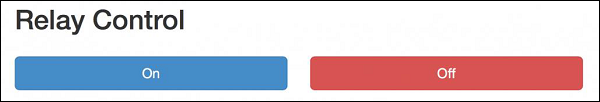
Try clicking the button on the web interface;
If you manage to make it work, congratulations, you just built a Wi-Fi-controlled light switch. /b11> Of course, through this project you can control more lights. /b12> Just make sure your relay supports the power you need for the device you want to control, and you're done.