Description of the Arduino board
May 15, 2021 Arduino
In this chapter, we'll look at the different components on the Arduino board. T he Arduino UNO board will be learned as it is the most popular in the Arduino board series. /b11> In addition, it is the best board to start using electronics and coding. /b12> Some boards look a little different from what is given below, but most of these components in Arduino are common.
Here are the circuits for the UNO board:
Here are the detailed parameters for the UNO board:
| Name | Parameters |
|---|---|
| Operating voltage | 5V |
| The input voltage | No external power supply or external 7V to 12V DC input is required to connect USB |
| The output voltage | 5V DC output and 3.3V DC output and external power input |
| Microprocessor | ATmega328 |
| Bootloader | Arduino Uno |
| Clock frequency | 16 MHz |
| Input voltage (recommended) | 7-12V |
| Input voltage (limit) | 6-20V |
| Support for USB interface protocol and power supply (no external power required) | |
| Support for ISP downloads | |
| Digital I/O port | 14 (6 PWM exits) |
| Simulate the input port | 6 |
| DC current I/O port | 40mA |
| DC current 3.3V port | 50mA |
| Flash memory | 32 KB (ATmega328) (0.5 KB for boot program) |
| Sram | 2 KB (ATmega328) |
| Eeprom | 1 KB (ATmega328) |
| Size | 75x55x15mm |
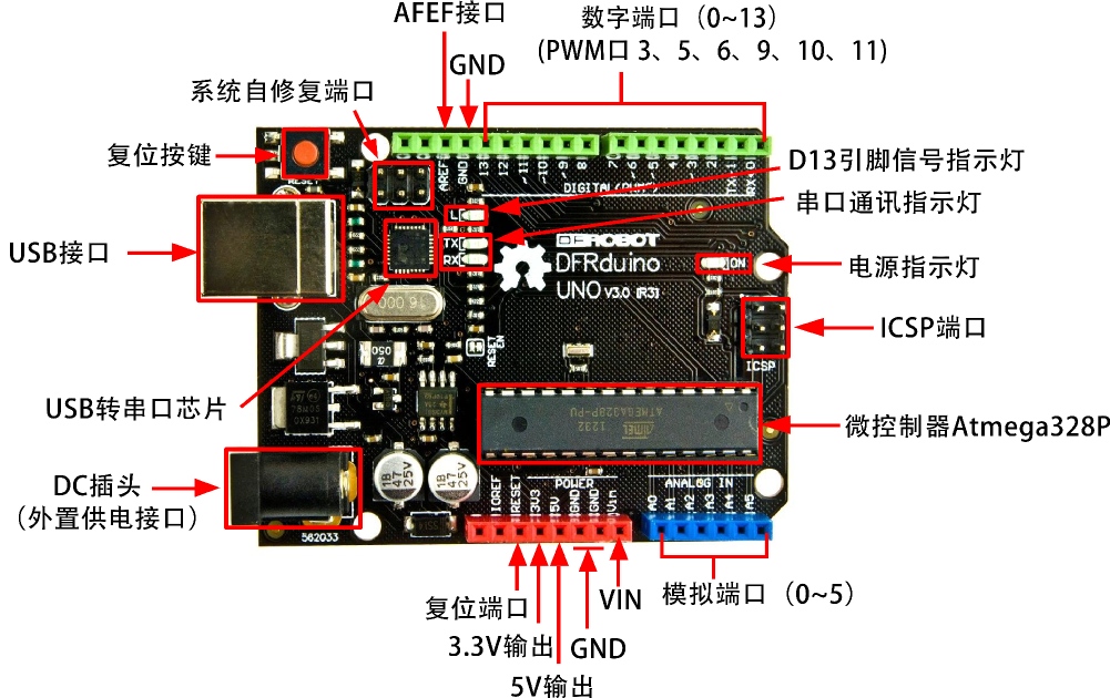
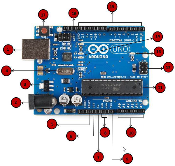
Here are the details of the UNO board:

|
Power USB The Arduino board can be powered by using a USB cable on your computer. All you need to do is connect the USB cable to the USB connector. |

|
Power (barrel socket) The Arduino board can be powered directly from the AC power supply by connecting it to a power plug. |

|
Regulator The function of the regulator is to control the voltage supplied to the Arduino board and to stabilize the DC voltage used by the processor and other components. |

|
Crystal oscillator Crystals help Arduino deal with time issues. H ow does Arduino calculate time? T he answer is, by using a crystal oscillator. T he number printed on top of the Arduino crystal is 16.000H9H. It tells us that the frequency is 16,000,000 Hz or 16MHz. |

|
Arduino reset You can reset your Arduino board, for example, to start your program from the start. T here are two ways to reset the UNO board. F irst, use the reset button (17) on the board. Second, you can connect the external reset button to the Arduino pin labeled RESET(5). |

|
Pins (3.3, 5, GND, Vin)
|

|
The analog pin The Arduino UNO board has six analog input pins, A0 to A5. These pins can read signals from analog sensors, such as humidity sensors or temperature sensors, and convert them to digital values that can be read by the microprocessor. |

|
Microcontroller Each Arduino board has its own microcontroller (11). Y ou can assume it as a board brain. T he main IC (integrated circuit) on Arduino is slightly different from the board-to-board. M icrocontrollers are usually ATMEL. B efore loading a new program from the Arduino IDE, you must know what ICs are on your board. T his information is located at the top of the IC. For more details about IC structures and capabilities, see data sheets. |

|
ICSP pin In most cases, ICSP(12) is an AVR, a microprogramming head of Arduino consisting of MOSI, MISO, SCK, RESET, VCC, and GND. I t is often referred to as the SPI (Serial Peripheral Interface) and can be considered an "extension" of the output. In fact, you are the host that subordinates the output device to the SPI bus. |

|
Power LED When you plug Arduino into power, this LED should light up to indicate that your board is properly powered on. If this light is not on, there is a problem with the connection. |

|
TX and RX LEDs On your board, you'll find two labels: TX (Send) and RX (Receive). T hey appear in two places on the Arduino UNO board. F irst, at digital pins 0 and 1, the indicator pin is responsible for serial communication. S econd, TX and RX LEDs (13). W hen sending serial data, the TX LED flashes at different speeds. T he flashing speed depends on the baud rate used by the board. RX flashes during reception. |

|
The number I/O The Arduino UNO board has 14 digital I/O pins (15), six of which provide PWM (pulse width modulation) outputs, which can be configured as digital input pins to read logical values (0 or 1), or as digital output pins to drive different modules, such as LEDs, relays, etc. Pins labeled "-" can be used to produce PWMs. |

|
AREF AREF stands for analog reference. It is sometimes used to set the external reference voltage (between 0 and 5 volts) as the upper limit of the analog input pin. |