Arduino wireless communication
May 15, 2021 Arduino
Table of contents
1. Receiver module specifications
2. Transmitter module specifications
6. Arduino code for the transmitter
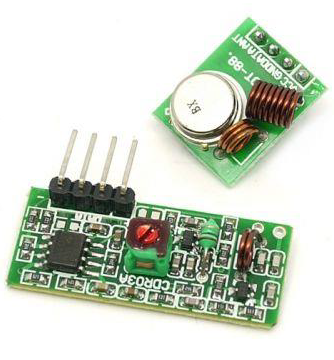
The wireless transmitter and receiver modules work at 315 Mhz. /b10> They can be easily loaded into breadboards and work well with microcontrollers to create a very simple wireless data link. /b11>With a pair of transmitters and receivers, the module will only be able to transfer data in one way, so you will need two pairs (different frequencies) as transmitter/receiver pairs.
Note - These modules are arbitrary and will receive quite a lot of noise. /b10> Both the transmitter and receiver work at the common frequency and do not have an ID.
Receiver module specifications
Operating voltage - DC5V
Static current - 4mA
Receive frequency - 315Mhz
Receive sensitivity - -105DB
Dimensions - 30 x 14 x 7mm
Transmitter module specifications
Emission distance - 20-200 m (different voltages, different results)
Operating voltage - 3.5-12V
Dimensions - 19 x 19mm
Operating mode - AM
Transfer rate - 4KB/S
Transmit power - 10mW
Emission frequency - 315Mhz
External antenna - 25cm normal multi-core or single-core line
Pin distribution from left to right - DATA; VCC; GND
The required component
You will need the following components:
- 2 × Arduino UNO board
- 1 × rf link transmitter
- 1 × rf link receiver
Program
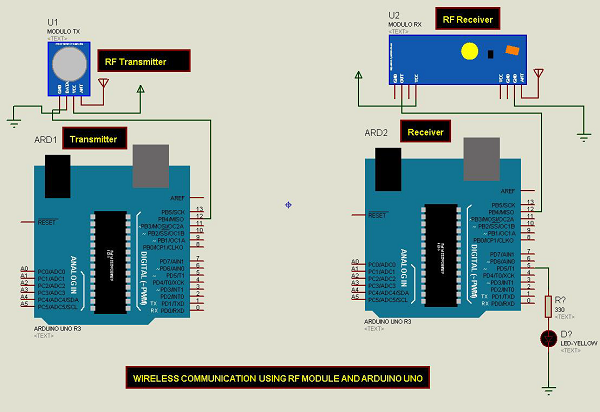
Connect according to the circuit diagram, as shown in the following image.
Sketch
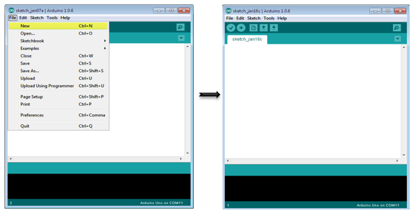
Turn on the Arduino IDE software on your computer. U se arduino to encode and control your circuitry. /b11> Open a new sketch file by clicking New.
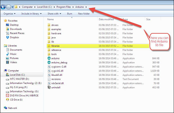
Note - You must include the keyboard library in the Arduino library file. /b10> Copy and paste the VirtualWire.lib file into the library folder, as shown in the highlighted section of the screenshot below.
Arduino code for the transmitter
//simple Tx on pin D12
#include <VirtualWire.h>
char *controller;

void setup() {
   pinMode(13,OUTPUT);
   vw_set_ptt_inverted(true);
   vw_set_tx_pin(12);
   vw_setup(4000);// speed of data transfer Kbps
}

void loop() {
   controller="1" ;
   vw_send((uint8_t *)controller, strlen(controller));
   vw_wait_tx(); // Wait until the whole message is gone
   digitalWrite(13,1);
   delay(2000);
   controller="0" ;
   vw_send((uint8_t *)controller, strlen(controller));
   vw_wait_tx(); // Wait until the whole message is gone
   digitalWrite(13,0);
   delay(2000);
}
Code description
This is a simple code. /b10> Send the character "1" first, the character "0" two seconds later, and so on.
The Arduino code for the receiver
//simple Rx on pin D12
#include <VirtualWire.h>

void setup() {
   vw_set_ptt_inverted(true); // Required for DR3100
   vw_set_rx_pin(12);
   vw_setup(4000); // Bits per sec
   pinMode(5, OUTPUT);
   vw_rx_start(); // Start the receiver PLL running
}

void loop() {
   uint8_t buf[VW_MAX_MESSAGE_LEN];
   uint8_t buflen = VW_MAX_MESSAGE_LEN;
   if (vw_get_message(buf, &buflen)) // Non-blocking {
      if(buf[0]=='1') {
         digitalWrite(5,1);
      }
      if(buf[0]=='0') {
         digitalWrite(5,0);
      }
   }
}
Code description
When the character "1" is received, the LED connected to pin 5 on the Arduino board lights up, and when the character "0" is received, the LED goes out.