Arduino servo motor
May 15, 2021 Arduino
Table of contents
A servo motor is a small device with an output shaft. /b10> By sending a encoded signal to the servo, the axis can be positioned at a specific angle. /b11> As long as the encoded signal exists on the input line, the servo maintains the adverb position of the axis. /b12> If the encoding signal changes, the angle position of the axis changes. /b13> In fact, it is used in radio-controlled aircraft to locate control surfaces, such as lifts and rudders. /b14> They are also used in radio-controlled cars, puppets and, of course, robots.
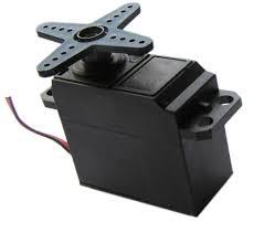
Servo is very useful in robots. /b10> The motors are small in size and have built-in control circuits that are very powerful relative to their size. /b11> Standard servo such as the Futaba S-148 has 42 oz/inch of torque, which is robust for its size. /b12> It also absorbs power proportional to the mechanical load. /b13> Therefore, light-load servo does not consume much energy.
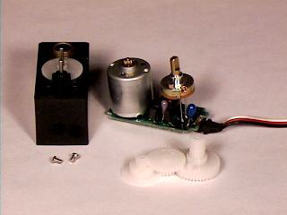
The inner bile of the servo motor is shown in the figure below. Y ou can see the control circuit, the motor, a set of gears and the housing. /b11>You can also see 3 wires connected to the outside. /b12> One is connected to the power supply (-5 volts), one is grounded, and the white line is the control line.
Servo motor work
The servo motor has some control circuits and a power generator (a variable resistor, also known as a power plant) connected to the output shaft. /b10> In the figure above, the poweror can be seen on the right side of the board. /b11> The switch allows the control circuit to monitor the current angle of the servo motor.
If the shaft is at the correct angle, the motor is switched off. /b10> If the circuit finds an incorrect angle, the motor is turned until it is at the desired angle. T he servo's output shaft can be moved around 180 degrees. T ypically, it is somewhere in the 210-degree range, however, it depends on the manufacturer. N ormal servo is taken at an angle of 0 to 180 degrees. Due to the mechanical stop on the main output gear, it cannot be mechanically turned farther.
The power applied to the motor is proportional to the distance it needs to travel. /b10> Therefore, if the shaft needs to be turned at a large distance, the motor will run at full speed. /b11> If only a small amount of rotation is required, the motor will operate at a lower speed. /b12> This is called proportional control.
How do I communicate the angle at which the servo should turn?
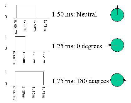
The control line is used to communicate the angle. /b10> This angle is determined by the duration of the pulse applied to the control line. /b11> This is called pulse-coded modulation. /b12> The servo expects to see a pulse every 20 milliseconds (0.02 seconds). /b13> The length of the pulse will determine the distance at which the motor rotates. /b14> For example, a 1.5-millisecond pulse will turn the motor to a 90-degree position (often referred to as a neutral position). /b15> If the pulse is shorter than 1.5 milliseconds, the motor turns the shaft closer to 0 degrees. /b16> If the pulse is longer than 1.5 milliseconds, the axis turns close to 180 degrees.
The required component
You will need the following components:
- 1 × Arduino UNO board
- 1 × servo motor
- 1 × ULN2003 drive IC
- 1 × 10K?resistor
Program
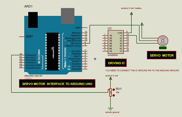
Connect according to the circuit diagram, as shown in the following image.
Sketch
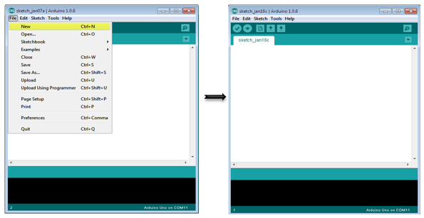
Turn on the Arduino IDE software on your computer. U se arduino to encode and control your circuitry. /b11> Open a new sketch file by clicking New.
Arduino code
/* Controlling a servo position using a potentiometer (variable resistor) */

#include <Servo.h>
   Servo myservo; // create servo object to control a servo
   int potpin = 0; // analog pin used to connect the potentiometer
   int val; // variable to read the value from the analog pin

void setup() {
   myservo.attach(9); // attaches the servo on pin 9 to the servo object
}

void loop() {
   val = analogRead(potpin);
   // reads the value of the potentiometer (value between 0 and 1023)
   val = map(val, 0, 1023, 0, 180);
   // scale it to use it with the servo (value between 0 and 180)
   myservo.write(val); // sets the servo position according to the scaled value
   delay(15);
}
Code description
Servo motors have three terminals: power, ground, and signal. /b10> The power cord is usually red and should be connected to the 5V pin on Arduino. /b11>The ground wire is usually black or brown and should be connected to one terminal of the ULAN2003 IC (10-16). /b12> To protect your Arduino board from damage, you will need some drive ICs to handle these. /b13> Here we use the ULN2003 IC to drive the servo motor. /b14> The signal pin is usually yellow or orange and should be connected to Arduino pin 9.
Connect the power generator
A voltage splittor is a resistor in a series circuit that scales the output voltage to a specific proportion of the applied input voltage. Here's the circuit diagram:
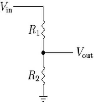
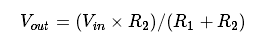
V out is the output level, depending on the input voltage (V in) and resistance (R 1 and R 2) applied. /b11> This means that the current flowing through R 1 will also flow through R 2 without being sedded. /b12> In the above equivalent, as the value of R changes, V out scales relative to the input voltage V in.
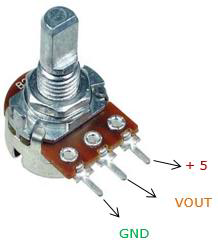
Typically, a power converter is a voltage splitter that uses a knob to scale the output voltage of a circuit based on the value of a variable resistance. It has three pins: GND, Signal, and .5V, as shown in the following image:
Results
By changing the NOP position of the planter, the servo motor changes its angle.