Arduino serial peripheral interface
May 15, 2021 Arduino
Table of contents
The Serial Peripheral Interface (SPI) bus is a system for serial communication that can use up to four conductors, typically three. /b10>One conductor is used for data reception, one conductor is used for data sending, one conductor is used for synchronization, and the other conductor is used to select the equipment to communicate with. /b11> It is a full duplegong connection, which means that data is sent and received at the same time. /b12> The maximum baud rate is higher than the Baud rate in the I2C communication system.
The SPI pin of the board
SPI uses the following four lines:
-
SCK - This is a host-driven serial clock.
-
MOSI - This is the host-driven main output/from input.
-
MISO - This is the host-driven main input/output.
-
SS - This is the select line from the machine.
Using the following functions, SPI.h. must be included
-
SPI.begin() - Initialize the SPI bus by setting SCK, MOSI, and SS to output, lowering SCK and MOSI, and pulling SS high.
-
SPI.setClockDivider ( splittor ) - Set the SPI clock splittor relative to the system clock. O n AVR-based boards, the available splittors are 2,4,8,16,32,64 or 128. The default SPI_CLOCK_DIV4, which sets the SPI clock to a quarter of the system clock (5 Mhz for a 20 MHz board).
-
Divider - It can be (SPI_CLOCK_DIV2, SPI_CLOCK_DIV4, SPI_CLOCK_DIV8, SPI_CLOCK_DIV16, SPI_CLOCK_DIV32, SPI_CLOCK_DIV64, SPI_CLOCK_DIV128).
-
SPI.transfer (val) - SPI transfers are based on simultaneous sending and receiving: the received data is returned in the receivedVal.
-
SPI.beginTransaction (speedMaximum, dataOrder, dataMode) - speedMaximum is clock, dataOrder (MSBFIRST or LSBFIRST), dataMode (SPI_MODE0,SPI_MODE1,SPI_MODE2 or SPI_MODE3).
There are four modes of operation in the SPI, as follows:
-
Mode 0 (default) - The clock is typically low (CPOL s 0) and the data is sampled during the transition from low to high (front) (CPHA s 0).
-
Mode 1 - The clock is typically low (CPOL s 0) and the data is sampled during the transition from high to low (back edge) (CPHA s 1).
-
Mode 2 - The clock is typically high (CPOL s 1) and the data is sampled during the transition from high to low (front) (CPHA s 0).
-
Mode 3 - The clock is typically high (CPOL s 1) and the data is sampled during the transition from low to high (back edge) (CPHA s 1).
-
SPI.attachInterrupt - A function called when data is received from the device from the primary device.
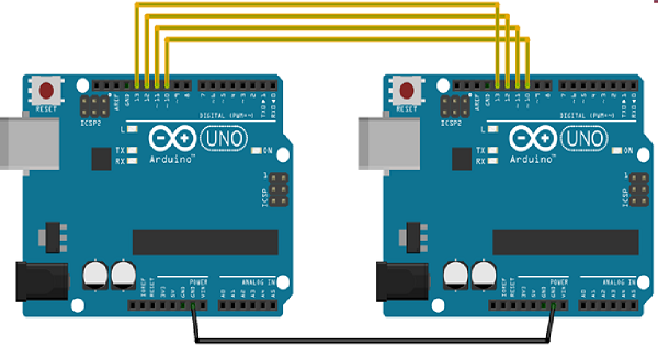
Now we connect the two Arduino UNO boards together;
- (SS): Pin 10
- (MOSI): Pin 11
- (MISO): Pin 12
- (SCK): Pin 13
Grounding is common. The following is an illustration of the connection between the two boards:
Let's look at SPI as a host and SPI as an example from the machine.
The SPI is the host
Example
#include <SPI.h>

void setup (void) {
   Serial.begin(115200); //set baud rate to 115200 for usart
   digitalWrite(SS, HIGH); // disable Slave Select
   SPI.begin ();
   SPI.setClockDivider(SPI_CLOCK_DIV8);//divide the clock by 8
}

void loop (void) {
   char c;
   digitalWrite(SS, LOW); // enable Slave Select
   // send test string
   for (const char * p = "Hello, world!\r" ; c = *p; p++) {
      SPI.transfer (c);
      Serial.print(c);
   }
   digitalWrite(SS, HIGH); // disable Slave Select
   delay(2000);
}
The SPI is the from the machine
Example
#include <SPI.h>
char buff [50];
volatile byte indx;
volatile boolean process;

void setup (void) {
   Serial.begin (115200);
   pinMode(MISO, OUTPUT); // have to send on master in so it set as output
   SPCR |= _BV(SPE); // turn on SPI in slave mode
   indx = 0; // buffer empty
   process = false;
   SPI.attachInterrupt(); // turn on interrupt
}
ISR (SPI_STC_vect) // SPI interrupt routine {
   byte c = SPDR; // read byte from SPI Data Register
   if (indx < sizeof buff) {
      buff [indx++] = c; // save data in the next index in the array buff
      if (c == '\r') //check for the end of the word
      process = true;
   }
}

void loop (void) {
   if (process) {
      process = false; //reset the process
      Serial.println (buff); //print the array on serial monitor
      indx= 0; //reset button to zero
   }
}