Arduino pulse width modulation
May 15, 2021 Arduino
Table of contents
Pulse width modulation or PWM is a common technique used to change the pulse width in a pulse string. /b10> PWM has many applications, such as control servo and speed controllers, that limit the effective power of motors and LEDs.
The fundamentals of PWM
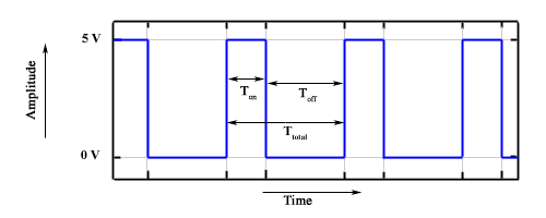
Pulse width modulation is basically a square wave that changes over time. /b10> The basic PWM signal is shown in the figure below.
There are many terms related to PWM:
-
On-Time - The duration of the time signal is longer.
-
Off-Time - The duration of the time signal is short.
-
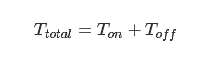
Period - represents the sum of the on time and shutdown time of the PWM signal.
-
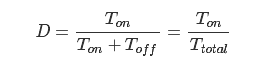
Duty Cycle - It is expressed as a percentage of the time signal that remains on during the PWM signal cycle.
Cycle
As shown in the figure, T on represents the on time, and T off represents the shutdown time of the signal. The period is the sum of on and off times and is calculated according to the following formula:
The space-to-air ratio
The mantivity is used to calculate the on time for a period of time. Using the period calculated above, the space ratio is calculated as:
AnalogWrite() function
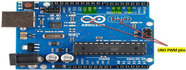
The analogWrite() function writes the analog value (PWM wave) to the pin. /b10> It can be used to light leDs at different brightnesses or to drive motors at various speeds. /b11>After calling the analogWrite() function, the pin produces a steady square wave that specifies the mantle ratio until the next call to analogWrite() or to digitalRead() or digitalWrite() on the same pin. /b12> The PWM signal frequency on most pins is approximately 490 Hz. /b13> On Uno and similar boards, pins 5 and 6 have frequencies of approximately 980Hz. /b14> Pins 3 and 11 on Leonardo also run at 980Hz.
On most Arduino boards (ATmega168 or ATmega328), this function works on pins 3, 5, 6, 9, 10 and 11. O n Arduino Mega, it works on pins 2-13 and 44-46. T he old Arduino ATmega 8 board only supported pins 9, 10 and 11 on analogWrite().
Arduino Due supports pins 2 through 13 and analogWrite() on pins DAC0 and DAC1. /b10> Unlike the PWM pins, DAC0 and DAC1 are digital-mode converters that are used as true analog outputs.
There is no need to call pinMode() to set the pin to output before calling analogWrite().
AnalogWrite() function syntax
analogWrite ( pin , value ) ;
value − the duty cycle: between 0 (always off) and 255 (always on).
value - the space ratio: between 0 (always on) and 255 (always off).
Example
int ledPin = 9; // LED connected to digital pin 9
int analogPin = 3; // potentiometer connected to analog pin 3
int val = 0; // variable to store the read value

void setup() {
   pinMode(ledPin, OUTPUT); // sets the pin as output
}

void loop() {
   val = analogRead(analogPin); // read the input pin
   analogWrite(ledPin, (val / 4)); // analogRead values go from 0 to 1023,
      // analogWrite values from 0 to 255
}