Arduino gradient LED
May 15, 2021 Arduino
Table of contents
This example demonstrates the ability to use the analogWrite() function to gradient LEDs. AnalogWrite uses pulse width modulation (PWM) to turn digital pins on and off very quickly at different ratios between on and off to produce a gradient effect.
The required component
You will need the following components:
- 1 × breadboard breadboard
- 1 × Arduino Uno R3
- 1 × LED
- 1 × 330-ohm resistor
- 2 × jumper
Program
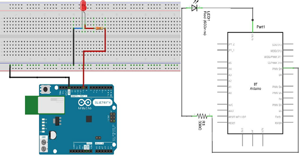
Connect the components on the breadboard according to the circuit diagram, as shown in the following image.
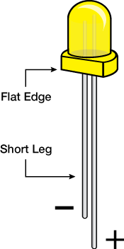
Note - To understand the polarity of the LED, take a closer look. The shorter of the two legs represent negative extremes toward the flat edge of the bulb.
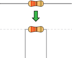
Components such as resistors need to bend their terminals to a 90-degree angle in order to fit the breadboard socket properly. You can also cut the terminals short.
Sketch
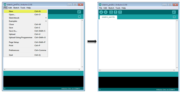
Turn on the Arduino IDE software on your computer. U se arduino to encode and control your circuitry. Open a new sketch file by clicking New.
Arduino code
/*
   Fade
   This example shows how to fade an LED on pin 9 using the analogWrite() function.

   The analogWrite() function uses PWM, so if you want to change the pin you're using, be
   sure to use another PWM capable pin. On most Arduino, the PWM pins are identified with
   a "~" sign, like ~3, ~5, ~6, ~9, ~10 and ~11.
*/

int led = 9; // the PWM pin the LED is attached to
int brightness = 0; // how bright the LED is
int fadeAmount = 5; // how many points to fade the LED by
// the setup routine runs once when you press reset:

void setup() {
   // declare pin 9 to be an output:
   pinMode(led, OUTPUT);
}

// the loop routine runs over and over again forever:

void loop() {
   // set the brightness of pin 9:
   analogWrite(led, brightness);
   // change the brightness for next time through the loop:
   brightness = brightness + fadeAmount;
   // reverse the direction of the fading at the ends of the fade:
   if (brightness == 0 || brightness == 255) {
      fadeAmount = -fadeAmount ;
   }
   // wait for 30 milliseconds to see the dimming effect
   delay(300);
}
Code description
After declaring pin 9 as an LED pin, there is no action in the setup() function of the code. The analogWrite() function that you will use in the main loop of your code will require two arguments: one tells the function which pin to write to and the other to represent the PWM value to write.
In order for the LED gradient to go out and on, gradually increase the PWM value from 0 (all the way off) to 255 (all the way on), then go back to 0 to complete the cycle. I n the sketch given above, the PWM value is set using a variable called brightness. Each time it passes through a loop, it increases the value of the variable faceAmount.
If brightness is at any extreme value (0 or 255) of its value, the faceAmount becomes negative. I n other words, if faceAmount is 5, it is set to -5. I f it is -5, then it is set to 5. The next time you go through the loop, this change will also cause Brightness to change direction.
AnalogWrite() can change the PWM value very quickly, so the delay at the end of the sketch controls the speed of the gradient. Try changing the value of the delay to see how it changes the gradient effect.
Results
You should see your LED brightness change gradually.