Arduino DC motor
May 15, 2021 Arduino
Table of contents
In this chapter, we will use the Arduino board (UNO) to connect different types of motors and show you how to connect the motor and drive it from the board.
There are three different types of motors:
- DC motor DC motor
- Servo motor servo motor
- Stepper motor stepper motor
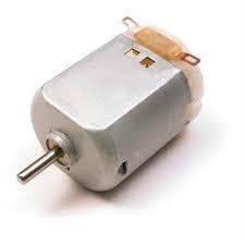
DC-Direct Motor is the most common type of motor. /b10> DC motors usually have only two leads, one positive and one negative. /b11> If you connect these two leads directly to the battery, the motor rotates. /b12> If you switch leads, the motor rotates in the opposite direction.
Warning - Do not drive the motor directly from the Arduino plate pin. /b10> This may damage the board. /b11> Use a drive circuit or IC.
We divide this chapter into three parts:
- Just let your motor spin
- Control the motor speed
- Controls the direction of rotation of the DC motor
The required component
You will need the following components:
- 1x Arduino UNO board
- 1x PN2222 transistor
- 1x small 6V DC motor
- 1x 1N4001 diode
- 1x 270-ohm resistor
Program
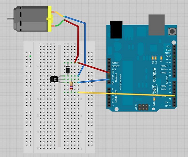
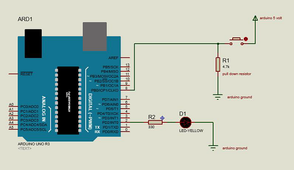
Connect according to the circuit diagram, as shown in the following image.
Precautions
When connecting, take the following precautions:
-
First, make sure that the transistors are connected in the correct way. A s shown in the figure, the flat plane of the transistor should face the Arduino plate.
-
Second, depending on the arrangement shown in the image, the striped end of the diode should be facing the power cord of .5V.
Arduino rotates the control code
int motorPin = 3;

void setup() {

}

void loop() {
   digitalWrite(motorPin, HIGH);
}
Code description
A transistor is like a switch that controls the power of a motor. /b10> Arduino Pin 3 is used to turn transistors on and off and is named "motorPin" in the sketch.
Results
When Arduino pin 3 becomes high, the motor rotates at full speed.
Motor speed control
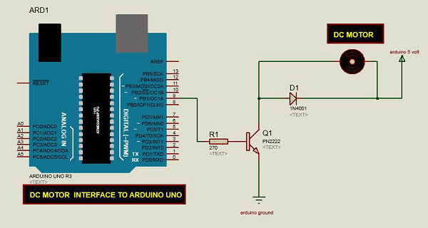
The following is a schematic of the DC motor connected to the Arduino plate.
Arduino code
int motorPin = 9;
void setup() {
pinMode(motorPin, OUTPUT);
Serial.begin(9600);
while (! Serial);
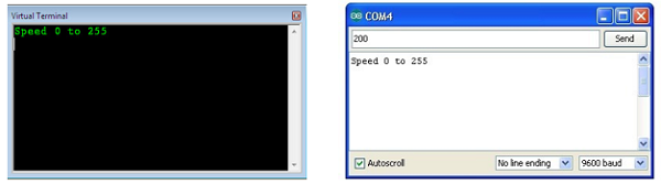
Serial.println("Speed 0 to 255");
}
void loop() {
if (Serial.available()) {
int speed = Serial.parseInt();
if (speed >= 0 && speed <= 255) {
analogWrite(motorPin, speed);
}
}
}
Code description
A transistor is like a switch that controls the power of a motor. /b10> Arduino Pin 3 is used to turn transistors on and off and is named "motorPin" in the sketch.
When the program starts, it prompts you to provide a value to control the speed of the motor. Y ou need to enter a value between 0 and 255 in the serial monitor.
In the Loop function, the command Serial.parseInt reads the number entered as text in the serial monitor and converts it to "int". Y ou can enter any number here. /b11> If the number is between 0 and 255, the "if" statement on the next line uses only that number for analog writing.
Results
The DC motor rotates at different speeds depending on the value received through the serial port (0 to 250).
The direction of rotation is controlled
In order to control the direction of rotation of the DC motor, there is no need to swap leads, and a circuit called the H-bridge can be used. /b10> The H-bridge is an electronic circuit that drives the motor in both directions. /b11> The H bridge is used in many different applications. /b12> One of the most common applications is the control of motors in robots. /b13> It is called the H bridge because it uses four transistors to connect, making the schematic look like an "H".
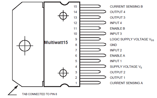
We will use the L298 H Bridge IC here. /b10> The L298 controls the speed and direction of both dc and stepper motors, and can control both motors at the same time. /b11> The rated current for each motor is 2A. /b12> However, under these currents, you will need to use a heatseed sheet.
The required component
You will need the following components:
- 1 × L298 Bridge IC
- 1 × dc motor
- 1 × Arduino UNO
- 1 × breadboard
- 10 × jumper
Program
The following is a diagram of the DC motor interface for the Arduino Uno board.
The figure above shows how to connect the L298 IC to control the two motors. /b10> Each motor has three input pins, Motor1's Input1 (IN1), Input2(IN2) and Enable1 (EN1);
Since in this example we only control one motor, we will connect Arduino to the IN1 (pin 5), IN2 (pin 7) and Enable1 (pin 6) of the L298 IC. /b10> Pins 5 and 7 are numeric, i.e. ON or OFF inputs, while pin 6 requires a pulse width modulation (PWM) signal to control motor speed.
The following table shows the direction in which the motor rotates according to the numeric values of IN1 and IN2.
| IN1 | IN2 | Motor behavior |
|---|---|---|
| Brake | ||
| 1 | Forward | |
| 1 | Back | |
| 1 | 1 | Brake |
Pin IN1 of the IC L298 is connected to Pin 8 of Arduino, while IN2 is connected to Pin 9. T hese two digital pins of Arduino control the direction of the motor. /b10> The EN A pin of the IC is connected to the PWM pin 2 of Arduino. /b11> This will control the speed of the motor.
In order to set the values of Arduino pins 8 and 9, we used the digitalWrite() function, and set the value of pin 2, we had to use the analogWrite() function.
The connection step
-
Connect the IC's 5V and ground to Arduino's 5V and ground, respectively.
-
Connect the motor to pins 2 and 3 of the IC.
-
Connect the IC's IN1 to Arduino's pin 8.
-
Connect the IC's IN2 to Arduino's pin 9.
-
Connect the EN1 of the IC to the pin 2 of Arduino.
-
Ground the SENS A pin of the ICD.
-
Connect Arduino using the Arduino USB cable and upload the program to Arduino using arduino IDE software.
-
Use a power supply, battery or USB cable to power the Arduino board.
Arduino code
const int pwm = 2 ; //initializing pin 2 as pwm
const int in_1 = 8 ;
const int in_2 = 9 ;
//For providing logic to L298 IC to choose the direction of the DC motor

void setup() {
   pinMode(pwm,OUTPUT) ; //we have to set PWM pin as output
   pinMode(in_1,OUTPUT) ; //Logic pins are also set as output
   pinMode(in_2,OUTPUT) ;
}

void loop() {
   //For Clock wise motion , in_1 = High , in_2 = Low
   digitalWrite(in_1,HIGH) ;
   digitalWrite(in_2,LOW) ;
   analogWrite(pwm,255) ;
   /* setting pwm of the motor to 255 we can change the speed of rotation
   by changing pwm input but we are only using arduino so we are using highest
   value to driver the motor */
   //Clockwise for 3 secs
   delay(3000) ;
   //For brake
   digitalWrite(in_1,HIGH) ;
   digitalWrite(in_2,HIGH) ;
   delay(1000) ;
   //For Anti Clock-wise motion - IN_1 = LOW , IN_2 = HIGH
   digitalWrite(in_1,LOW) ;
   digitalWrite(in_2,HIGH) ;
   delay(3000) ;
   //For brake
   digitalWrite(in_1,HIGH) ;
   digitalWrite(in_2,HIGH) ;
   delay(1000) ;
}
Results
The motor first runs clockwise (CW) for 3 seconds and then counterclockwise (CCW) for 3 seconds.